China Top 10 CNC Machining Companies Why Tolerances Matter?

Time:2026-10-05 Author:Liam
0%

China’s CNC machining sector has become a critical manufacturing base for aerospace, medical, automotive, and industrial components. The International Federation of Robotics reported that China installed more industrial robots than any other country in 2023. That automation supports repeatable production, but it does not eliminate engineering judgment. A robot can repeat an inaccurate process perfectly.

This raises a practical question: what is the importance of tolerances in cnc machining? Tolerances define the acceptable limits around a part’s dimensions, position, form, and surface condition. A shaft measured at 20.00 millimeters may fail if its mating bore requires a controlled fit. A hole displaced by only 0.05 millimeters can affect assembly, sealing, or fatigue performance. ISO 286-1 provides internationally recognized principles for limits and fits, while ASME Y14.5 guides geometric dimensioning and tolerancing practices. These standards help manufacturers communicate requirements clearly across design, machining, inspection, and supply chains.

The “China Top 10 CNC Machining Companies” should therefore be judged beyond machine count or advertised accuracy. Reliable suppliers should explain their inspection methods, calibration systems, material controls, and process capability evidence. NIST measurement guidance emphasizes that measurement results must consider uncertainty, not only displayed values. Important detail. A certificate alone does not prove process stability. A tighter tolerance is not automatically better, either. It can increase cutting time, tool wear, inspection costs, and rejected parts. This is where experienced manufacturers show maturity: they balance function, risk, cost, and repeatability. Some supplier claims may still require deeper verification. That weakness deserves attention, because trustworthy machining begins with evidence, not impressive language.
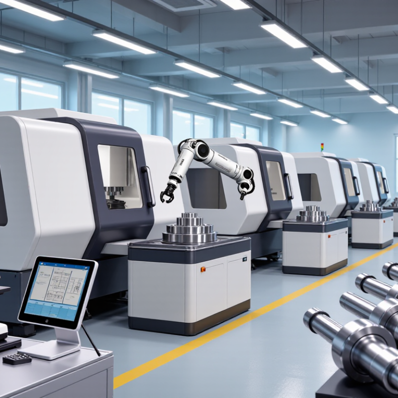
China Top 10 CNC Machining Companies Why Tolerances Matter?

CNC Tolerances Defined: Why ±0.01 mm Can Affect Part Function

China Top 10 CNC Machining Companies: Why Tolerances Matter?

A CNC tolerance defines how far a finished dimension may vary from its drawing value. For example, ±0.01 mm allows a 20.00 mm shaft to measure between 19.99 and 20.01 mm. That range looks tiny. In assembly work, it can decide whether parts slide, bind, or leak. A bearing seat with excessive clearance may vibrate. A hole that is too tight can damage the mating pin during installation.

Experienced machining teams do not treat every dimension equally. They study material, cutting tools, temperature, measurement methods, and the part’s actual function. Aluminum may expand during cutting, while hardened steel can produce more tool wear. A skilled inspector checks critical features with calibrated gauges, micrometers, or coordinate measuring equipment. Still, a perfect report does not guarantee a perfect assembly. Design assumptions can be wrong, and I have seen tolerance stacks expose problems that individual measurements missed.

Tips: Mark functional dimensions clearly, then assign practical tolerances to noncritical surfaces. Ask the machinist whether ±0.01 mm is necessary for each feature. Tighter tolerances often increase machining time, inspection effort, and cost. Keep datums consistent across drawings and inspection plans. Test a sample assembly before approving full production. Do not rely only on supplier claims; request measurement records and review the method used. A tolerance decision should reflect real movement, load, temperature, and maintenance conditions.

ISO 2768 and ASME Y14.5: The Standards Behind CNC Accuracy

ISO 2768 and ASME Y14.5 define how CNC accuracy should be interpreted. ISO 2768 assigns general tolerances when a drawing lacks individual limits. ASME Y14.5 uses geometric dimensioning and tolerancing to control form, orientation, location, and runout. These systems prevent vague instructions from reaching the machine shop.

Small details matter. A shaft may meet its diameter tolerance but still fail because its axis is misaligned. Experienced engineers establish datums before programming and connect each critical feature to an inspection method. A coordinate measuring machine can verify position, while calibrated micrometers check simple dimensions. Inspection records should identify the equipment, operator, date, and measurement results.

Standards guide decisions, but they do not replace engineering judgment. A general ISO tolerance may be acceptable for a cover, yet unsuitable for a bearing seat. ASME Y14.5 can describe the functional relationship between holes, but unclear datum selection may create disputes. This is where reliable CNC suppliers show practical knowledge. They review drawings, question conflicting requirements, and confirm whether the tolerance is manufacturable. I have seen projects become expensive because designers tightened every dimension without checking function. Tighter is not always better. Sometimes, the drawing needs revision before cutting begins.

China Top 10 CNC Machining Companies Why Tolerances Matter? - ISO 2768 and ASME Y14.5: The Standards Behind CNC Accuracy

Comparison Dimension ISO 2768 ASME Y14.5 Practical CNC Machining Implication
Primary purpose Provides general tolerances for dimensions without individually specified tolerances. Defines the language and rules of geometric dimensioning and tolerancing, commonly called GD&T. Use ISO 2768 for default dimensional limits and ASME Y14.5 for functional geometric requirements.
Typical drawing reference A drawing may state “ISO 2768-m” or “ISO 2768-mK,” depending on the applicable tolerance classes. A drawing typically identifies the applicable edition and uses datum references, feature control frames, and symbols. The title block and general notes should clearly identify which standard governs inspection.
Linear dimension tolerance, 0.5–3 mm Class f: ±0.05 mm; Class m: ±0.10 mm; Class c: ±0.20 mm; Class v: ±0.50 mm. No equivalent default value is prescribed by ASME Y14.5; the limit must be specified by a size tolerance or GD&T requirement. Small features can require explicit tolerances when fit, sealing, or motion is important.
Linear dimension tolerance, over 6–30 mm Class f: ±0.10 mm; Class m: ±0.20 mm; Class c: ±0.50 mm; Class v: ±1.00 mm. The standard provides rules for interpreting tolerances and geometric controls, not a universal size-tolerance table. A general tolerance may be suitable for non-critical dimensions, while mating features normally need individual control.
Linear dimension tolerance, over 120–400 mm Class f: ±0.30 mm; Class m: ±0.50 mm; Class c: ±1.20 mm; Class v: ±2.50 mm. Large-feature accuracy depends on the specified dimension tolerance, datum scheme, geometric control, and inspection method. Thermal expansion, workholding, machine travel, and measurement uncertainty become increasingly important.
Tolerance classes Four commonly used classes are fine (f), medium (m), coarse (c), and very coarse (v). Does not use ISO 2768’s f, m, c, and v general-tolerance classes. Selecting a class affects manufacturing cost, inspection effort, and the risk of unnecessary rejection.
Straightness and flatness ISO 2768-2 provides general geometric tolerances for features without individually specified geometric tolerances; the applicable edition and status should be verified. Controls straightness and flatness through GD&T feature control frames and the specified tolerance zone. Flatness controls a surface without requiring a datum; it is different from parallelism and profile.
Perpendicularity and parallelism May be covered by general geometric-tolerance provisions when the drawing invokes the relevant ISO 2768 designation. Specified relative to a datum or datum reference frame using dedicated GD&T symbols. Datum-based controls are more suitable when assembly orientation affects product performance.
Position of holes and features General dimensional tolerances alone do not communicate the complete functional location requirement of a hole pattern. True position can define a cylindrical tolerance zone and relate the feature to a datum reference frame. Position tolerance often improves assembly reliability compared with separately toleranced X and Y dimensions.
Datum system General ISO dimensional tolerances do not provide the same datum reference framework used by ASME GD&T. Uses primary, secondary, and tertiary datum references to establish how a part is oriented and located for verification. A clear datum scheme helps align machining, fixture design, and coordinate measuring machine inspection.
Circular runout and total runout Not normally communicated through a simple ISO 2768 linear general tolerance. Provides dedicated runout controls referenced to a datum axis or datum system. Runout is important for rotating shafts, bearing seats, sealing surfaces, and concentric features.
Drawing interpretation A general note applies only where an individual tolerance is not already stated and where the standard is properly invoked. Interpretation depends on the complete GD&T scheme, including symbols, modifiers, datums, and applicable defaults. Manufacturers and inspectors should confirm the drawing revision and governing standard before production.
Inspection approach Commonly verified with calibrated hand tools, gauges, optical equipment, or coordinate measuring equipment according to feature size and risk. Requires inspection aligned with the datum reference frame and the defined geometric tolerance zone. Inspection planning should be agreed before machining to avoid disputes over setup and measurement alignment.
Effect on manufacturing cost Tighter general classes usually require better process control and increase inspection requirements. Well-designed GD&T can reduce unnecessary tight tolerances while protecting functional requirements. Specify tight tolerances only on functional features to balance accuracy, lead time, and cost.
Best application Suitable for uncomplicated parts and non-critical features when a consistent default tolerance is needed. Suitable for complex assemblies, interchangeable parts, precision interfaces, and requirements involving orientation or location. Many drawings use general tolerances for ordinary features and explicit GD&T for critical characteristics.

Note: ISO 2768 values shown for linear dimensions are representative values from ISO 2768-1 tolerance classes. The governing drawing, material condition, feature type, standard edition, and inspection method should always be confirmed before production.

IT7–IT9 Fits Explained: How Micron-Level Variation Changes Assembly

In China’s top CNC machining companies, tolerance control often decides whether a precision assembly works smoothly. IT7, IT8, and IT9 are tolerance grades, not complete fits. Their actual limits depend on nominal diameter and ISO 286 tables. IT7 permits less variation than IT9. The difference may be only several microns, but that is enough to change assembly behavior.

A hole marked H7 paired with a shaft marked g6 usually creates controlled clearance. The shaft enters without force, while movement remains limited. Change the shaft to p6, and the same nominal size may require pressing. A small tolerance shift can increase friction, distort a thin wall, or prevent insertion entirely. For example, a 20 mm component with a few microns of variation may feel perfect at room temperature, then tighten after heating. Metal expands. Lubricant also changes friction.

Reliable machining requires more than a capable machine. Operators verify tool wear, cutting temperature, datum control, and measuring equipment. A calibrated CMM or bore gauge can reveal a 6-micron drift that hand gauges miss. Surface roughness and burrs matter too. They can imitate an incorrect fit. In shop practice, I have seen drawings treated as exact promises, although every process has variation. That assumption needs challenge. Holding IT7 may require stable fixturing, controlled temperature, and statistical process checks. IT9 may suit less demanding locations, but it is not automatically safe for every assembly.

China Top 10 CNC Machining Companies: Why Tolerances Matter?

IT7–IT9 Fits Explained: How Micron-Level Variation Changes Assembly

The chart shows representative total tolerance widths in micrometres (µm) for ISO 286 tolerance grades across common nominal-size ranges. IT7, IT8, and IT9 are calculated from the ISO tolerance-unit method and rounded to one decimal place. A larger IT grade permits more dimensional variation, which can increase clearance, misalignment, vibration, or assembly difficulty. The actual hole-and-shaft fit also depends on the selected fundamental deviations and not on the IT grade alone.

Reference basis: ISO 286 tolerance-unit calculation, where i = 0.45∛D + 0.001D and IT7 = 16i, IT8 = 25i, IT9 = 40i.

China’s Top 10 CNC Machining Companies Compared by Tolerance Capability

China Top 10 CNC Machining Companies: Why Tolerances Matter?

Comparing China’s top ten CNC machining companies requires more than reading a ±0.01 mm claim. Tolerance capability depends on material, part size, thermal control, tooling, and inspection methods. Industry benchmarks commonly place standard CNC tolerances near ±0.05 mm, while controlled precision work may reach ±0.01–0.025 mm. These figures are practical references, not guarantees.

A fair comparison should examine Cpk results, repeatability, surface finish, and measurement equipment. The NIST/SEMATECH e-Handbook explains that Cpk measures how consistently a process stays within specification limits. A supplier reporting only its best inspection result offers weak evidence. ASME Y14.5-2018 also separates design tolerance from manufacturing capability, a distinction that many purchasing teams overlook.

ISO 230-2:2014 provides methods for evaluating machine-tool positioning accuracy and repeatability. Those results can reveal whether a quoted tolerance survives production, not just one sample. The strongest companies usually document calibrated CMM inspections, temperature records, material traceability, and corrective actions. Small details matter.

Still, comparison tables can mislead. A ±0.01 mm result on a short aluminum feature does not equal the same result on hardened steel. My practical concern is simple: rankings should show tolerance by material, dimension, batch size, and process. Otherwise, “top ten” sounds more certain than the evidence allows.

Inspection Data: CMM Accuracy, ±0.005 mm Measurement, and Quality Control

In precision machining, tolerance is more than a number on a drawing. A bore may allow only ±0.005 mm. That limit can affect assembly, sealing, and service life. It also tests the inspection process.

A coordinate measuring machine, or CMM, records the part against defined datums. Its accuracy must be suitable for the required tolerance. A machine cannot reliably judge a ±0.005 mm feature if its uncertainty is too large. Calibration records, temperature control, probe qualification, and fixture stability all matter. Even a clean inspection room needs attention.

Inspection data should show measured values, not only pass or fail results. For example, a bore measured at +0.003 mm reveals more than a green status label. Repeated measurements can expose drift, operator influence, or poor alignment. The measurement strategy should match the drawing’s functional requirements. A misplaced datum can produce precise but misleading results.

Experienced quality teams review trends across batches. They check CMM repeatability and compare results with gauges when practical. Small differences may be acceptable, but unexplained differences deserve investigation. Sometimes the process is stable, yet the measurement method is weak. That possibility is easy to overlook.

Tolerance decisions should balance function, manufacturing capability, and inspection risk. Extremely tight limits may increase cost without improving performance. Honest engineering leaves room for questioning the original requirement. Reliable suppliers document these decisions and preserve traceable inspection records. That evidence supports better production choices.

FAQS

What does a ±0.01 mm tolerance mean?

It allows a dimension to vary by 0.01 mm above or below its drawing value.

Why can a small tolerance change part function?

A loose bearing seat may vibrate during operation. A tight hole may damage its mating pin. Small errors can block assembly completely.

Should every feature use a ±0.01 mm tolerance?

No. Apply tight limits only to functional features. Noncritical surfaces often need practical, wider tolerances. Overtight requirements can increase machining and inspection costs.

What factors can change CNC machining accuracy?

Material expansion, cutting temperature, tool wear, and fixture stability all matter. Aluminum may expand during cutting. Hardened steel can accelerate tool wear. Temperature control is easy to underestimate.

What are IT7, IT8, and IT9 tolerance grades?

They are tolerance grades, not complete fits. Their limits depend on the nominal diameter and applicable tolerance tables. IT7 allows less variation than IT9. A few microns can change assembly behavior.

How can hole and shaft fits affect installation?

An H7 hole with a g6 shaft commonly provides controlled clearance. The shaft should enter without force. A p6 shaft may require pressing instead. Surface roughness and burrs can imitate an incorrect fit.

Can a CMM reliably inspect a ±0.005 mm feature?

Only when its accuracy and uncertainty suit that tolerance. Calibration, probe qualification, temperature, and fixture stability must be controlled. A precise-looking result may still be misleading. The datum could be wrong.

What inspection information should a quality report include?

It should show measured values, datums, equipment details, and traceable records. A bore measured at +0.003 mm reveals useful process information. Repeated measurements can expose drift or operator influence. Pass or fail alone is insufficient.

Should a sample assembly be tested before full production?

Yes, whenever fit or movement is important. Test the parts under realistic load, temperature, lubrication, and maintenance conditions. Room-temperature assembly may change after heating. Design assumptions sometimes fail.

Conclusion

CNC machining tolerances define how closely a manufactured part must match its intended dimensions, and even a small deviation such as ±0.01 mm can affect fit, movement, sealing, strength, and overall product performance. The importance of tolerances becomes clearer when considering the question, “what is the importance of tolerances in cnc machining?” Standards such as ISO 2768 and ASME Y14.5 provide structured methods for specifying and interpreting dimensional accuracy, while IT7–IT9 fits explain how micron-level variations influence clearances, interference, and assembly reliability.

This overview compares China’s top 10 CNC machining companies by their tolerance capabilities, focusing on process control, equipment stability, and inspection methods rather than brand reputation. It also highlights the role of coordinate measuring machines, including measurement capability around ±0.005 mm, in verifying critical dimensions. By balancing precision requirements, material behavior, production volume, and inspection data, manufacturers can achieve dependable quality without imposing unnecessary machining costs.

Liam

Liam

Liam is a dedicated marketing professional with a profound expertise in the industry, where he excels at highlighting the unique advantages of our core products. With a keen understanding of market trends and consumer needs, Liam frequently updates our company’s professional blog, providing......